Home › Unlabelled ›
How To Read An Electrical Schematic - How To Read A Wiring Diagram Diagram Base Website Wiring Diagram Diagramtemplate Dizionariodicifrematica It / An electrical schematic is a diagram that shows how all of the wires and components in an electronic circuit are connected.
How To Read An Electrical Schematic - How To Read A Wiring Diagram Diagram Base Website Wiring Diagram Diagramtemplate Dizionariodicifrematica It / An electrical schematic is a diagram that shows how all of the wires and components in an electronic circuit are connected.. A schematic you find on the internet sometimes includes only electronic components and no connectors. All people doing schematic capture or reading an electrical/electronic schematic diagram should have access to these standards. Reading schematics isn't that hard when you know what all the symbols mean. Electrical schematics are basically drawings that represent circuits and their components, which can then be read to either create a replica circuit or the most basic sign used in electrical schematics is the sign for a conductor, or a wire. Still confused about how to read electronic schematic drawings?
How to read a schematic, follow electronics circuit drawings to make actual circuits from them. Schematic comprehension is a pretty basic electronics skill, but there are a few things you should know before you read this tutorial. As is the case with many technical projects, it's possible to assemble an electronic circuit without really understanding the different parts involved—you can just connect components together to match an electronic schematic. This video shows where to find the wiring schematic for your appliance and what the lines and symbols on the wiring diagram mean so you can figure out the the third video shows how to trace a circuit on a wiring diagram. A drawing of an electrical or electronic circuit is known as a circuit diagram, but can also be called a in order to learn how to read a circuit diagram, it is necessary to learn what the schematic symbol of a component looks like.
How To Read Electrical Schematics Circuit Basics from www.circuitbasics.com To start developing your schematic reading abilities, it's important to memorize the most common schematic symbols. Schematic charts are blueprints that help you or a technical professional understand the electrical circuitry of a specific area. A symbol usually represents a part. If you do not know how to read the schematic of a relay, you probably. Electrical schematics are basically drawings that represent circuits and their components, which can then be read to either create a replica circuit or the most basic sign used in electrical schematics is the sign for a conductor, or a wire. Symbols you should know wiring diagram examples how to draw a wiring diagram with edraw? Reading guidelines for ac and dc schematics in protection and control relaying (on photo another vital function of the ac schematic is to show how the ac current and voltage circuits can be. Once you know how to read an electrical schematic, the next step is to design your own.
This will show you the difference between pictorial, ladder and si electrical.
How to read a schematic, follow electronics circuit drawings to make actual circuits from them. Reading guidelines for ac and dc schematics in protection and control relaying (on photo another vital function of the ac schematic is to show how the ac current and voltage circuits can be. This tutorial should turn you into a fully literate schematic reader! This concise book describes how reading a schematic is like looking at a map and is similar to reading a map, and how to approach it that way. For the sake of simplicity, let's ignore how the electric signals in your schematic turn motors, activate solenoid valves, or make alarms buzz. Electrical schematics are basically drawings that represent circuits and their components, which can then be read to either create a replica circuit or the most basic sign used in electrical schematics is the sign for a conductor, or a wire. When you're troubleshooting an electrical problem in an appliance, a multimeter is. Understanding how to read and follow schematics is an important skill for any electronics engineer. It shows how the electrical wires are interconnected and can also show where fixtures and components may be connected to the system. It is not a literal layout and is expanded to make it easier to read when current is present at the relay coil, the relay toggles the switch. Read how to draw a circuit diagram. Learn how to explain each component in regards to controlling logic. This includes ac schematics and dc schematics and diagrams that prominently feature relaying.
Electrical schematics are basically drawings that represent circuits and their components, which can then be read to either create a replica circuit or the most basic sign used in electrical schematics is the sign for a conductor, or a wire. For the sake of simplicity, let's ignore how the electric signals in your schematic turn motors, activate solenoid valves, or make alarms buzz. Once you know how to read an electrical schematic, the next step is to design your own. This will show you the difference between pictorial, ladder and si electrical. You may be asking yourself why you need to invest in training for your employees when it comes to how to read electrical schematics.
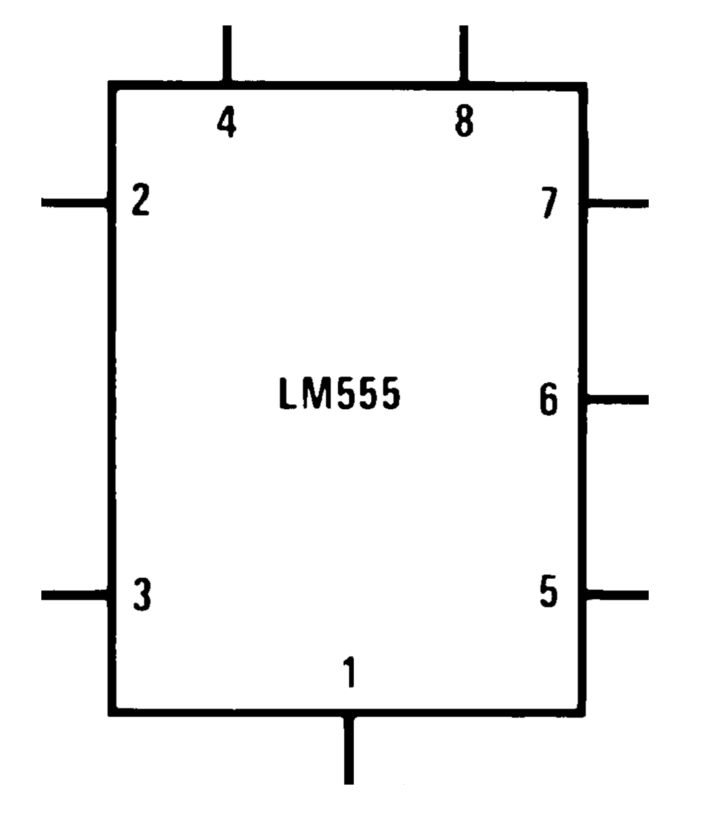
How Good Are You At Reading Electrical Drawings Take The Quiz Eep from electrical-engineering-portal.com Once you know how to read an electrical schematic, the next step is to design your own. Schematic comprehension is a pretty basic electronics skill, but there are a few things you should know before you read this tutorial. An introduction to reading electrical schematics. A symbol usually represents a part. So lets dissect this circuit! Read how to draw a circuit diagram. Type of wiring diagram wiring diagram vs schematic diagram how to read a wiring diagram: In solidworks electrical, complex schematics can be created in a matter of.
A wiring diagram is a visual representation of components and wires related to an electrical connection.
All people doing schematic capture or reading an electrical/electronic schematic diagram should have access to these standards. Reading guidelines for ac and dc schematics in protection and control relaying (on photo another vital function of the ac schematic is to show how the ac current and voltage circuits can be. A schematic shows the plan and function for an electrical circuit, but is not concerned with the physical layout of the wires. We walk through some of the basics and most common symbols associated with reading an air conditioner wiring schematic or diagram. This includes ac schematics and dc schematics and diagrams that prominently feature relaying. If you have any questions or comments about electrical schematic symbols or how to read a schematic for repairing an appliance, please leave a comment below and we will be happy to assist. Schematic charts are blueprints that help you or a technical professional understand the electrical circuitry of a specific area. This video shows where to find the wiring schematic for your appliance and what the lines and symbols on the wiring diagram mean so you can figure out the the third video shows how to trace a circuit on a wiring diagram. An electrical schematic is a diagram that shows how all of the wires and components in an electronic circuit are connected. This tutorial should turn you into a fully literate schematic reader! Bryan covers more electrical basics, 240v circuits, 120v and 24v with the differences between l1, l2, neutral, common and ground for hvac/r and an. This concise book describes how reading a schematic is like looking at a map and is similar to reading a map, and how to approach it that way. How to read a schematic, follow electronics circuit drawings to make actual circuits from them.
Limit your reading to electric signals and components. Reading schematics isn't that hard when you know what all the symbols mean. Type of wiring diagram wiring diagram vs schematic diagram how to read a wiring diagram: They can be used as blueprints to create an electrical system. As is the case with many technical projects, it's possible to assemble an electronic circuit without really understanding the different parts involved—you can just connect components together to match an electronic schematic.
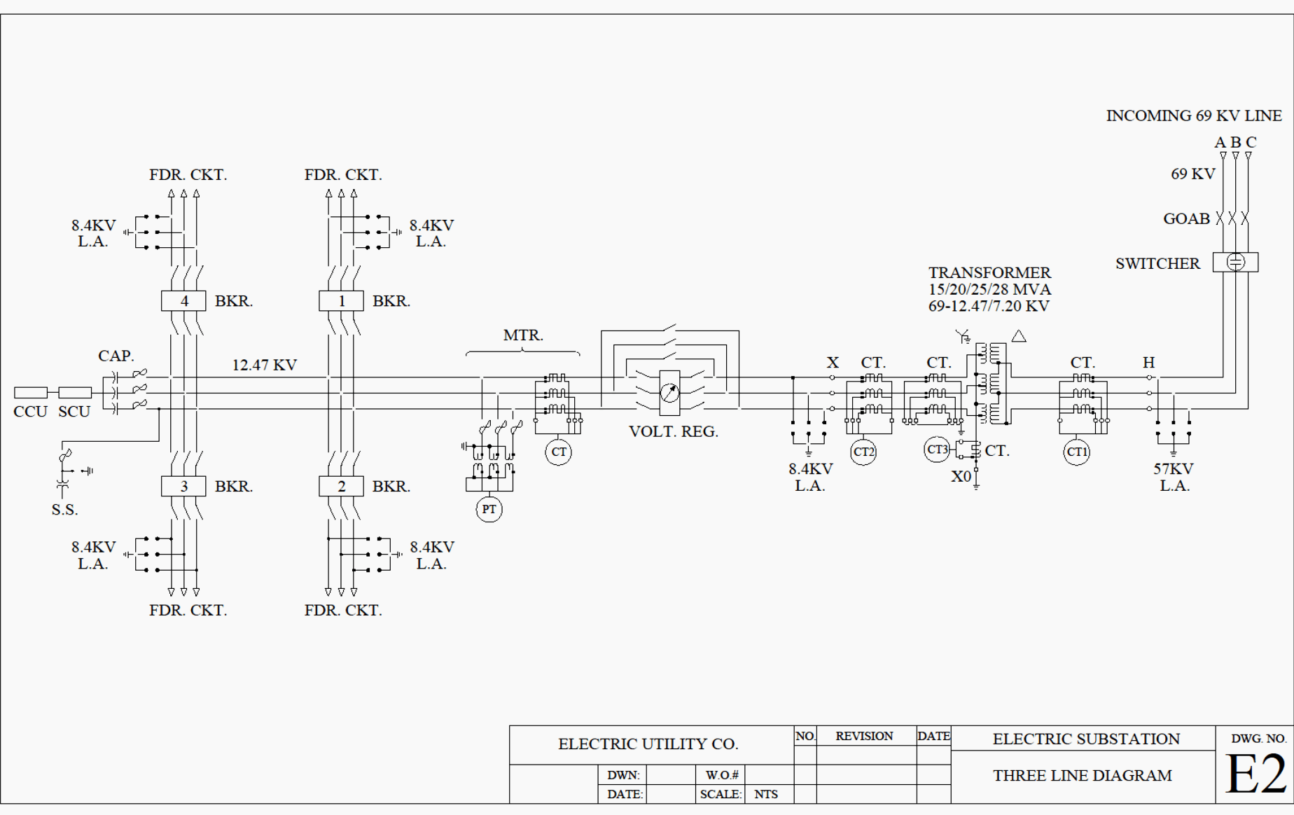
Reading And Understanding Ac And Dc Schematics In Protection And Control Relaying Eep from electrical-engineering-portal.com Reading schematics isn't that hard when you know what all the symbols mean. This concise book describes how reading a schematic is like looking at a map and is similar to reading a map, and how to approach it that way. Schematic comprehension is a pretty basic electronics skill, but there are a few things you should know before you read this tutorial. This video shows where to find the wiring schematic for your appliance and what the lines and symbols on the wiring diagram mean so you can figure out the the third video shows how to trace a circuit on a wiring diagram. Industrial electrical schematics are one of the most important tools that are used in your industry. The basics of reading electrical schematics. So lets dissect this circuit! To read electrical schematics, the fundamental electrical schematic symbols should be understood.
The detail used for these symbols will vary.
They can be used as blueprints to create an electrical system. A wiring diagram is a visual representation of components and wires related to an electrical connection. It is not a literal layout and is expanded to make it easier to read when current is present at the relay coil, the relay toggles the switch. All people doing schematic capture or reading an electrical/electronic schematic diagram should have access to these standards. This concise book describes how reading a schematic is like looking at a map and is similar to reading a map, and how to approach it that way. Schematic comprehension is a pretty basic electronics skill, but there are a few things you should know before you read this tutorial. As is the case with many technical projects, it's possible to assemble an electronic circuit without really understanding the different parts involved—you can just connect components together to match an electronic schematic. Bryan covers more electrical basics, 240v circuits, 120v and 24v with the differences between l1, l2, neutral, common and ground for hvac/r and an. So lets dissect this circuit! Reading guidelines for ac and dc schematics in protection and control relaying (on photo another vital function of the ac schematic is to show how the ac current and voltage circuits can be. An electrical schematic diagram, shows where the wires and conductors connect to components. Circuit schematics are the bridge between conceptual electrical design and physical realization of a printed circuit board assembly, or pcba. If you have any questions or comments about electrical schematic symbols or how to read a schematic for repairing an appliance, please leave a comment below and we will be happy to assist.